Tan Gia Bao products are truly game changers. Their stainless steel pipes not only help us streamline operations but also improve overall efficiency. High quality, reliable and durable, they are a valuable addition to our projects!
Mr. ThiCEO
Choosing Tan Gia Bao Steel is one of the best decisions we have made. Their commitment to quality and customer service is unmatched. The stainless steel pipes we purchased have become an indispensable part of our production process and greatly improved our productivity!
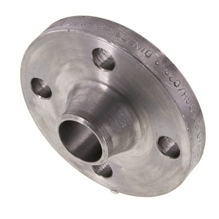
DIN 2635 Welding Neck Flanges are flanges with a welding neck, designed to connect to pipes through a neck weld, to ensure a secure and leak-proof connection. This type of flange has a neck that extends from the flange face outwards and is welded directly to the pipe. This transfers the load from the flange to the pipe, reducing the stress concentration at the base of the flange and ensuring the stability of the piping system.
Applications
DIN 2635 Welding Neck Flanges are commonly used in industries that require high strength and high pressure resistance, such as:
Oil and Gas Industry: Used in oil and gas transmission systems, including pipelines for crude oil, natural gas, and refined petroleum products.
Chemical industry: Applied in systems for conveying highly corrosive liquids and gases.
Energy Industry: Used in power plants, including steam and hot water systems.
Shipbuilding Industry: Used in piping systems on ships.
Food and beverage industry: Applied in food production and processing systems where hygiene and corrosion resistance are required.
Standards
DIN 2635 is the German standard for weld neck flanges. This standard defines specifications such as dimensions, thickness, and material of flanges, ensuring their suitability and safety when used in industrial applications.
Materials: Carbon steel, stainless steel, alloy steel, and other special alloys.
Sizes: Available from 1/2 inch to 24 inches.
Pressure: Designed for high pressures, commonly used in pressure systems from PN 6 to PN 40.
Standard: According to DIN 2635 standard.
DIN 2635 Welding Neck Flanges are the optimal choice for piping systems that require high strength, pressure resistance and good corrosion resistance. With wide applications in many industries, this flange ensures safety and efficiency in connecting and conducting liquids and gases in complex systems.
DIN 2635 Welding Neck Flanges Size and Thickness Table
Nominal Size (Inch)
Diameter (D)
Thickness (T)
Height (H)
Diameter of Bore (d)
Bolt Circle Diameter (BCD)
Number of Bolts
Diameter of Bolts (d1)
1/2″
90
11.2
40
15
60
4
12
3/4″
105
12.7
44
20
70
4
12
1″
115
14.2
47
25
80
4
12
1 1/4″
125
15.7
51
32
90
4
12
1 1/2″
140
16.8
53
40
100
4
12
2″
150
17.8
57
50
120
4
12
2 1/2″
180
20.2
64
65
140
4
16
3″
190
21.3
68
80
150
4
16
4″
230
23.9
78
100
180
8
16
5″
255
25.4
85
125
210
8
16
6″
280
26.9
90
150
240
8
20
8″
345
29.0
106
200
295
8
20
10″
405
30.6
118
250
355
12
20
12″
485
33.3
133
300
425
12
23
14″
535
35.8
146
350
485
12
25
16″
595
38.4
159
400
545
16
25
18″
635
41.0
171
450
600
16
29
20″
700
43.2
184
500
660
20
29
24″
815
47.7
210
600
775
20
32
Note:
Diameter (D): Outside diameter of the flange.
Thickness (T): Thickness of flange.
Height (H): Height from flange to weld neck.
Diameter of Bore (d): Diameter of the drilled hole.
Bolt Circle Diameter (BCD): Bolt circle diameter.
Number of Bolts: Number of bolts required.
Diameter of Bolts (d1): Diameter of bolts.
Material summary table for DIN 2635 Welding Neck Flanges